
Why Is Precision Assembly Critical for a Large Tandem Press Brake?
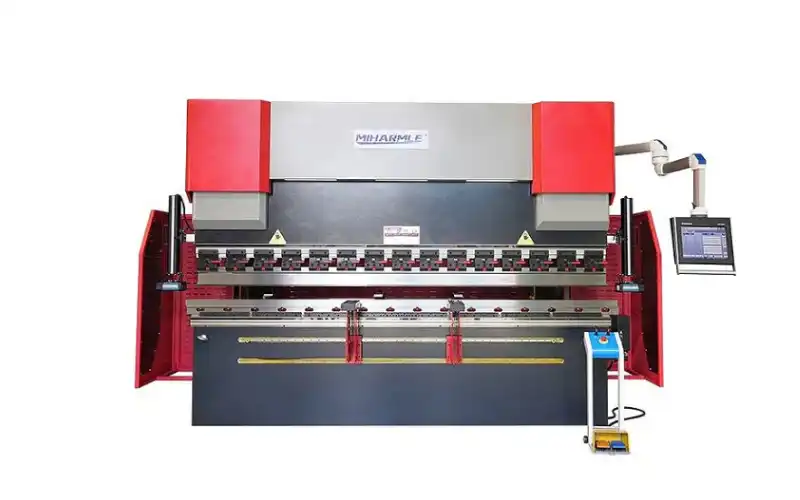
A Tandem Press Brake combines two CNC press brakes to bend extra-long and heavy workpieces as one coordinated system.
This creates a much greater installation and calibration challenge than a conventional single press brake.
For example, when two machines form one extended bending line, small differences in machine level, ram position, tooling height, bed alignment, or deflection compensation can accumulate across the total bending length.
The result may be:
- Uneven bending angles
- Different angles between the left and right sections
- Excessive center deviation
- Twisting of long workpieces
- Poor dimensional consistency
- Increased correction and rework
For this reason, the accuracy of a large Tandem Press Brake begins long before the first production part is bent.
It starts with precision assembly and geometric alignment.

Step 1: Establish a Precise Machine Foundation
A heavy-duty tandem system requires a stable installation environment.
Before final machine alignment, the foundation and installation area should be checked according to the machine manufacturer’s requirements.
The two press brakes must then be positioned so their working areas form a consistent bending reference.
For tandem systems, installers need to consider not only the level of each individual machine but also the relationship between the two machines.
A machine that is correctly leveled individually may still create bending problems if its working reference does not align with the adjacent press brake.
Step 2: Align the Two Press Brake Beds
Bed alignment is one of the most important stages of tandem assembly.
The lower working surfaces of Press Brake A and Press Brake B should create a consistent reference along the combined bending length.
Technicians may use precision measuring equipment such as:
precision levels, straightedges, laser measurement systems, dial indicators, and other alignment instruments.
The objective is to minimize relative height and alignment differences between the two machines.
For long workpieces, even small deviations can become visible in the final bending result.
Step 3: Check Ram and Tooling Alignment
After the machine beds are aligned, attention moves to the upper working system.
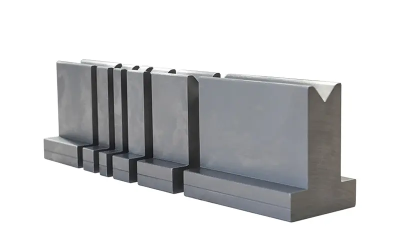
The ram, punch holders, punches, lower dies, and clamping system must work together as a continuous bending line.
Technicians should check:
- Ram parallelism
- Punch height consistency
- Die height consistency
- Tool centerline
- Clamping accuracy
- Transition between the two machines
This is especially important around the junction area between Press Brake A and Press Brake B.
If the tooling reference changes at this point, the long workpiece may show different bending results on each side.
Step 4: Calibrate Multi-Axis Synchronization
Mechanical alignment establishes the physical reference. CNC synchronization maintains that relationship during motion.
A large CNC Tandem Press Brake may coordinate multiple bending axes across the two machines.
In a simplified configuration:
Machine A → Y1 + Y2
Machine B → Y3 + Y4
Linear scales or other position-feedback devices monitor actual ram positions and return this information to the CNC system.
The control process follows a continuous loop:
Command → Movement → Position Feedback → Error Comparison → Correction
The objective is to keep all relevant bending axes within the machine’s specified synchronization tolerance throughout approach, bending, decompression, and return.
This calibration should be completed before evaluating final bending accuracy.
Why Does a Tandem Press Brake Need Crowning?
Even when the machines are perfectly aligned, another problem appears when bending long workpieces: deflection.
Under bending load, the ram, bed, tooling, and machine structure experience elastic deformation.
Without suitable compensation, the bending angle in the center of a long workpiece may differ from the bending angle near the ends.
This is where a press brake crowning system becomes important.
Crowning introduces a calculated compensation along the bending length to counteract deformation under load.
The goal is not simply to make the machine bed “curved.”
The goal is:
To achieve a more uniform bending angle across the entire workpiece under actual bending load.
Mechanical vs CNC-Controlled Crowning
Large press brakes may use different compensation architectures.
Mechanical Crowning
A mechanical crowning system commonly uses wedges distributed along the machine bed.
Adjusting their relative positions changes the compensation profile along the bending length.
This solution can be robust and effective when properly calibrated.
CNC-Controlled Crowning
With CNC-controlled crowning, the controller can calculate or command compensation according to bending parameters.
Depending on the machine design, inputs may include:
- Material
- Thickness
- Bending length
- Bending force
- V-die opening
- Tooling configuration
The operator can then fine-tune the compensation based on actual test-bending results.
For large tandem applications with frequently changing jobs, CNC-controlled adjustment can make setup more convenient.
How Is Crowning Calibrated on a Tandem Press Brake?
Crowning calibration should be treated as a complete bending-system calibration rather than an isolated setting.
1. Verify Mechanical Geometry
Machine level, bed alignment, ram parallelism, tooling and synchronization should be confirmed first.
Crowning should not be used to hide an underlying mechanical alignment problem.
2. Install and Inspect the
Recommended reading:
How Multi-Axis Mechanical Synchronization Works in CNC Tandem Press Brakes